Copyright ©1995 by NeXT Computer, Inc. All Rights Reserved.
| 7 |
NeXTbus Device Drivers
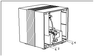
| NeXTbus is the interface bus supported by all NeXTcube and original NeXT computers. NeXTbus boards, such as the CPU and NeXTdimensionTMboards, plug into slots in the back of these computers and communicate over the NeXTbus. As Figure 7-1 shows, NeXTbus computers have four slots, numbered 0, 2, 4, and 6. The CPU board is always in slot 0. The remaining slots are available for other NeXTbus boards.
Note: NeXTstationTMcomputers don't have a NeXTbus or any expansion slots. |
|
| Figure 7-1. NeXTbus Slot Order
To be able to communicate with other NeXTbus boards, your computer's CPU board must have a NeXTbus Interface Chip (NBICTM). All NeXTcubes and 68040 Upgrade Boards have NBICs; however, original NeXT computers that still have the 68030 processor might not. See the NeXTbus Development Kit Installation Guide (part of the NeXTbus Development Kit) for instructions if you need to install an NBIC onto a 68030 board. |
| NeXTbus Address Space |
| Each NeXTbus board has access to two sections of the NeXTbus physical address space: the board address space and the slot address space that correspond to its slot. The board address space of each slot is 256 megabytes, from 0xs0000000 to 0xsfffffff, where s is the slot number; the slot address space of each slot is 16 megabytes at addresses 0xfs000000 to 0xfsffffff. Every register that your driver must read or write appears in either the board or the slot address space; the specification for your hardware should tell you exactly which physical address you must use. |
| Warning: | The addresses 0xs200c000 to 0xs200cfff, where s is 2, 4, or 6, are intercepted by logic on the CPU board; some CPU boards also intercept addresses 0xs1000000 to 0xs1ffffff, where s is 2, 4, or 6. Writing to these intercepted addresses can cause errors. If your driver needs access to information at these addresses, your board must be configured to accept addresses for the next higher slot, as described in the gray box later in this chapter. | |
| Figure 7-2 shows the NeXTbus physical address space. As the figure shows, the NeXTbus architecture allows for up to 15 slots, each with up to 272 megabytes of physical address space. | ||
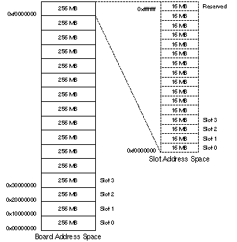 | ||
| Figure 7-2. NeXTbus Address Space | ||
| To read or write a hardware address, your driver must first map the physical address into a virtual one. "Mapping from Physical to Virtual Memory Addresses," later in this chapter, describes how to perform this mapping. |
| Writing Code to Control the Hardware |
| This section discusses some of the considerations for writing code that controls NeXTbus hardware. Before you write any code, you should test the hardware with BusProbeTM, an application in the NeXTbus Development Kit.
Using BusProbe BusProbe is a NeXTSTEP application that lets you read and write any address on a NeXTbus board. BusProbe is useful in all phases of driver writing. When you first start, it can help you verify the address of each register. As you write your server, you can test sequences of reads and writes with BusProbe before you put the code into your server. Later, BusProbe can help you when you're testing or debugging your server. You can use the repeat and autoincrement features to clear areas of memory on the board or for other repetitive tasks. BusProbe lets you choose the board or slot address space that you want to use. For this reason, you should specify an offset into this address space, not the whole address. Before you're ready to write any code, try reading from and writing to every register on your NeXTbus board. This will help you verify the address and format of each register. While you're writing your driver, you can use BusProbe to manually enter the actions that you think your driver will have to take. Once you've made sure the actions work, you can put the code to do them into your driver.
Mapping from Physical to Virtual Memory Addresses Use the routine map_addr() to turn a physical address into a virtual memory address that your driver can use. For example, to set a flag on a 32-bit register at address 0x100 in the slot address space of a NeXTbus board (physical address 0xfs000100), you would use the following code: |
![]() #define REG_ADDR 0xf0000100
#define REG_ADDR 0xf0000100
![]() volatile unsigned int *reg;
volatile unsigned int *reg;
![]() reg = (unsigned int *)map_addr(REG_ADDR | (slot_number << 24), 4);
reg = (unsigned int *)map_addr(REG_ADDR | (slot_number << 24), 4);
![]() *reg |= FLAG;
*reg |= FLAG;
| For a description of the physical address space, see the previous section, "NeXTbus Address Space."
Transferring Data NeXTbus boards can transfer data in up to three sizes: bytes (8 bits), halfwords (16 bits), and words (32 bits). You usually store bytes in unsigned char structures, halfwords in unsigned short structures, and words in unsigned int structures. |
| Warning: | Systems based on the 68040 processor don't allow you to read or write using a larger data structure than the device width. For example, you can't write a 32-bit quantity into an 8-bit register; you must use an 8-bit quantity such as an unsigned char. | |
| Burst transfers (transfers of 16 bytes with one instruction) are turned off by default for addresses that are mapped using map_addr(). (This is a side effect of map_addr() making the memory noncacheable, which is preferable when dealing with devices.) To perform a burst read or write on an address mapped with map_addr(), you must write assembly code that calls the 68040's MOVE16 instruction. Because MOVE16 reads or writes the bytes in 32-bit chunks, your hardware must be 32 bits wide. Note that the 68030 doesn't have a MOVE16 instruction and doesn't support burst writes. You can also enable burst transfers while using BusProbe by turning "Cache Inhibit" off. | ||
| Note: You can't currently use DMA (direct memory access) in a NeXTbus driver. Instead, you must use programmed (direct) I/O. | ||
| If your driver needs to read or write the addresses that are intercepted by the CPU board (0xs200c000 to 0xs200cfff and 0xs1000000 to 0xs1ffffff, where s is 2, 4, or 6), the NBIC on your board must be configured to accept the addresses for the next higher slot (3, 5, or 7).
You can't directly configure the NBIC from your driver; it must be done locally on your board. Specifically, the board must set the IGNSID0 bit (bit 28) of its own NBIC Control register to 1. Then, in your driver, you can address both the slot and board address spaces of the board with the next higher slot number. |
| NeXTbus Byte Ordering
Depending on your hardware, bytes might be swapped within a word. For example, if you read a word on your NeXTbus board that contains "0x12345678", your driver might see "0x78563412". You can determine whether byte order is an issue for your driver by consulting the designers of and documentation for your board, and by testing reads and writes using BusProbe. BusProbe does not change byte ordering, so if the reads and writes work with BusProbe, they should work the same way in your driver. The code below is an example of reversing byte order. In this example, the programmer wants to check whether bit 7 in a word is 1 by performing a bitwise OR with the word and 0x00000080. However, on a board that swaps bytes, the programmer has to switch the first and fourth bytes (0x80 and 0x00), producing 0x80000000. |
![]() volatile unsigned int *my_register;
volatile unsigned int *my_register;
![]() int reg_size = 4; /* # of bytes in the space to be mapped */
int reg_size = 4; /* # of bytes in the space to be mapped */
![]() my_register = (unsigned int *)map_addr((MY_ADDR | (slot_num << 24)),
my_register = (unsigned int *)map_addr((MY_ADDR | (slot_num << 24)),
![]() reg_size);
reg_size);
![]() if (probe_rb(my_register))
if (probe_rb(my_register))
![]() /* Make sure the Valid field is set */
/* Make sure the Valid field is set */
![]() if ( !(*my_register & 0x80000000)) /* byte-reversed 00000080 */
if ( !(*my_register & 0x80000000)) /* byte-reversed 00000080 */
![]() return FALSE;
return FALSE;
| Writing an Interrupt Handler
If your driver must directly detect interrupts, you must provide an interrupt handler. Your interrupt handler can be called whenever any NeXTbus board interrupts, not just when a board controlled by your driver interrupts. For this reason, your interrupt handler must check whether your driver's hardware generated the interrupt. If it did, your driver must handle the interrupt, stop the hardware from generating this interrupt, and return true. If your driver's hardware did not generate the interrupt, your interrupt handler must do nothing and return false. To stop NeXTbus hardware from generating an interrupt, write a 1 to bit 7 of the Interrupt Mask byte. This byte is discussed later in this chapter. |
| Warning: | Your interrupt handler (and any function it might call) must not sleep. See Chapter 6 for more details on precautions that interrupt handlers must take. | |
| Because interrupt handlers execute on behalf of the hardware, they have no knowledge of which user process they're working for. Thus, they can't use anything to do with a user process. | ||
| You install interrupt handlers using install_polled_intr(), and remove them using uninstall_polled_intr(). | ||
| The following example illustrates an interrupt handler. |
![]() #define SLOT_INTR_BIT 0x80
#define SLOT_INTR_BIT 0x80
![]() #define SLOTCOUNT 4
#define SLOTCOUNT 4
![]() /* In the following macro, slotid is half the slot #. */
/* In the following macro, slotid is half the slot #. */
![]() #define nbic_regs(slotid) (caddr_t)(0xf0ffffe8 | ((slotid)<<25)
#define nbic_regs(slotid) (caddr_t)(0xf0ffffe8 | ((slotid)<<25)
![]() mydriver_var_t my_var[SLOTCOUNT];
mydriver_var_t my_var[SLOTCOUNT];
![]() . . .
. . .
![]() sp = &my_var[slotid];
sp = &my_var[slotid];
![]() sp->nbic_addr=(unsigned char *)map_addr(nbic_regs(slotid), 24);
sp->nbic_addr=(unsigned char *)map_addr(nbic_regs(slotid), 24);
![]() . . .
. . .
![]() int my_intr(void)
int my_intr(void)
![]() {
{
![]() int slotid;
int slotid;
![]() volatile unsigned char *intr_reg, *mask_reg;
volatile unsigned char *intr_reg, *mask_reg;
![]() /*
/*
![]() * Figure out if we really handle this interrupt.
* Figure out if we really handle this interrupt.
![]() * Interrupts at level 5 are polled, so we have to
* Interrupts at level 5 are polled, so we have to
![]() * check the interrupt byte associated with the
* check the interrupt byte associated with the
![]() * hardware slots we control. slotid 1 corresponds
* hardware slots we control. slotid 1 corresponds
![]() * to hardware slot 2, slotid 2 to hardware slot 4,
* to hardware slot 2, slotid 2 to hardware slot 4,
![]() * and slotid 3 to hardware slot 6.
* and slotid 3 to hardware slot 6.
![]() */
*/
![]() for (slotid = 1; slotid < SLOTCOUNT; slotid++)
for (slotid = 1; slotid < SLOTCOUNT; slotid++)
![]() {
{
![]() if (my_var[slotid].is_ours) {
if (my_var[slotid].is_ours) {
![]() intr_reg = my_var[slotid].nbic_addr;
intr_reg = my_var[slotid].nbic_addr;
![]() if (*intr_reg & SLOT_INTR_BIT)
if (*intr_reg & SLOT_INTR_BIT)
![]() break;
break;
![]() }
}
![]() }
}
![]() /* If we couldn't handle the interrupt, leave now. */
/* If we couldn't handle the interrupt, leave now. */
![]() if (slotid == SLOTCOUNT)
if (slotid == SLOTCOUNT)
![]() return FALSE; /* Poll code should try next handler */
return FALSE; /* Poll code should try next handler */
![]() /*
/*
![]() * At this point some device-dependent code is necessary to
* At this point some device-dependent code is necessary to
![]() * reset the interrupt condition so that the device does
* reset the interrupt condition so that the device does
![]() * not continue to try to interrupt the CPU. Here we
* not continue to try to interrupt the CPU. Here we
![]() * disable the interrupt by clearing the mask bit.
* disable the interrupt by clearing the mask bit.
![]() */
*/
![]() mask_reg = intr_reg + 4;
mask_reg = intr_reg + 4;
![]() *mask_reg = 0; /* Mask it off. */
*mask_reg = 0; /* Mask it off. */
![]() /* Handle the interrupt. */
/* Handle the interrupt. */
![]() . . .
. . .
![]() /* Schedule a routine to react to the interrupt.*/
/* Schedule a routine to react to the interrupt.*/
![]() kern_serv_callout(&instance,
kern_serv_callout(&instance,
![]() (void (*)(void *))my_func,
(void (*)(void *))my_func,
![]() (void *)sp);
(void *)sp);
![]() return TRUE; /* We fielded the interrupt, so no
return TRUE; /* We fielded the interrupt, so no
![]() other driver should be polled. */
other driver should be polled. */
![]() }
}
![]() . . .
. . .
![]() install_polled_intr(I_BUS, my_intr);
install_polled_intr(I_BUS, my_intr);
| NeXTbus Board Registers |
| This section discusses the standard NeXTbus registers that your driver might have to read or write. For more information on the NeXTbus, see the NeXTbus Specification. For information on the NeXTbus Interface Chip (NBIC), see the NeXTbus Interface Chip Specification.
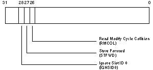
CPU Board NBIC Registers The only NBIC register on the CPU board that you might need to write to is the NBIC Control register, which has three defined bits. The only bit you might need to modify, however, is the Store Forward bit.
NBIC Control Register |
 |
| Figure 7-3. NBIC Control Register
The CPU board's NBIC Control register is at address 0x02020000. Bit 28, Ignore Slot ID 0 (IGNSID0), controls how much NeXTbus address space a board uses. It's set to 1 during initialization so that the CPU board takes up two slots worth of addresses. Bit 27 is the Store Forward (STFWD) control bit. At power up, it's enabled (set to 1). When enabled, Store Forward causes the CPU board's NBIC to immediately acknowledge writes, without waiting for the other NeXTbus board to write the data. This is called a store and forward write transaction. It speeds up transaction time, since the CPU doesn't have to wait for your board to write data. The disadvantage of store and forward write is that you won't receive any notification of write errors. Thus, unless your hardware is completely reliable, store and forward write can be dangerous. Bit 26 is the Read Modify Cycle Collision (RMCOL) bit. It's not appropriate to access this register on the CPU board.
Other NeXTbus Board Registers On every NeXTbus board, 6 bytes of identification and interrupt information are at addresses 0xfsffffe8 to 0xfsfffffc, where s is the slot number of the board. |
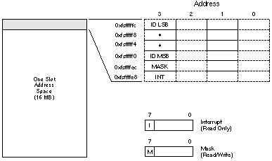 |
| Figure 7-4. Sample NeXTbus Slot Address Space
If your NeXTbus board uses an NBIC, then addresses 0xfsfffff0 through 0xfsfffffc correspond to the NBIC ID register, address 0xfsffffec is the Interrupt register, and 0xfsffffe8 is the Interrupt Mask register.
Identification Bytes (NBIC ID Register) |
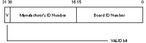 |
| Figure 7-5. NBIC ID Register
Identification bytes give information that identifies the type of NeXTbus board. Your driver should read them during its initialization to see whether it should take control of this board. The four Identification bytes are read-only bytes that contain a board ID number, a manufacturer's ID number, and a VALID bit. Unless the VALID bit is 1, none of the identification and interrupt information is valid. When the VALID bit is 1, the ID numbers are valid and your driver can use them to identify the board. Since each byte is mapped to a separate 32-bit word, your driver has to read four separate words (or bytes, if your hardware supports byte-wide reads) to get all the identification information. Figure 7-6 shows the Identification byte locations in the NeXTbus slot address space. |
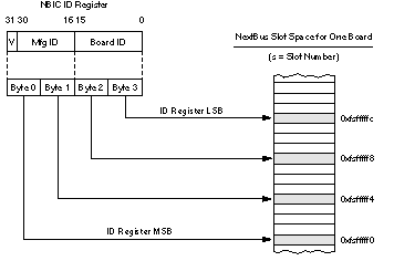 |
| Figure 7-6. Identification Bytes in the NeXTbus Slot Space
If your driver can't perform byte reads, you have to find the correct byte in each word or halfword. If your driver doesn't have to reverse the byte order, you can simply address the last byte of the word as an unsigned char. If you do have to reverse the byte order, you must right-shift each word or halfword to move the byte you want to read from the most significant to the least significant byte. The following example shows how to read the Identification bytes. |
![]() volatile unsigned int *id_start;
volatile unsigned int *id_start;
![]() int id_size = 16; /* # of bytes in the space to be mapped */
int id_size = 16; /* # of bytes in the space to be mapped */
![]() id_start=(unsigned int *)map_addr((0xf0fffff0 | (slotid << 25)),
id_start=(unsigned int *)map_addr((0xf0fffff0 | (slotid << 25)),
![]() id_size);
id_size);
![]() if (probe_rb(id_start))
if (probe_rb(id_start))
![]() {
{
![]() if (ids_ok(id_start, MY_MFG_ID, MY_BRD_ID))
if (ids_ok(id_start, MY_MFG_ID, MY_BRD_ID))
![]() my_var[slotid].present = TRUE;
my_var[slotid].present = TRUE;
![]() }
}
![]() #define HI_BYTE(n) ((n) >> 8)
#define HI_BYTE(n) ((n) >> 8)
![]() #define LO_BYTE(n) ((n) & 0xff)
#define LO_BYTE(n) ((n) & 0xff)
![]() /*
/*
![]() * Check the ID on the remote board to see if it matches ours. The
* Check the ID on the remote board to see if it matches ours. The
![]() * ID fields are spread out over four words from 0xFsFFFFF0 through
* ID fields are spread out over four words from 0xFsFFFFF0 through
![]() * 0xFsFFFFFC, with the valid data appearing in bits 0 through 7.
* 0xFsFFFFFC, with the valid data appearing in bits 0 through 7.
![]() */
*/
![]() boolean_t
boolean_t
![]() ids_ok(volatile unsigned int *id_begin, int board_id, int mfg_id)
ids_ok(volatile unsigned int *id_begin, int board_id, int mfg_id)
![]() {
{
![]() volatile unsigned int *current_word = id_begin;
volatile unsigned int *current_word = id_begin;
![]() /* Make sure the Valid field is set */
/* Make sure the Valid field is set */
![]() if ( !(*current_word & 0x00000080))
if ( !(*current_word & 0x00000080))
![]() return FALSE;
return FALSE;
![]() /* test high byte of mfg ID, ignoring the Valid field */
/* test high byte of mfg ID, ignoring the Valid field */
![]() if ( ((*current_word) & 0x7f) != HI_BYTE(mfg_id) )
if ( ((*current_word) & 0x7f) != HI_BYTE(mfg_id) )
![]() return FALSE;
return FALSE;
![]() ++current_word; /* Move to next word */
++current_word; /* Move to next word */
![]() /* test low byte of the mfg ID */
/* test low byte of the mfg ID */
![]() if ( (*current_word) != LO_BYTE(mfg_id) )
if ( (*current_word) != LO_BYTE(mfg_id) )
![]() return FALSE;
return FALSE;
![]() ++current_word; /* Move to next word */
++current_word; /* Move to next word */
![]() /* test high byte of the board ID */
/* test high byte of the board ID */
![]() if ( (*current_word) != HI_BYTE(board_id) )
if ( (*current_word) != HI_BYTE(board_id) )
![]() return FALSE;
return FALSE;
![]() ++current_word; /* Move to next word */
++current_word; /* Move to next word */
![]() /* test low byte of the board ID */
/* test low byte of the board ID */
![]() if ( (*current_word) != LO_BYTE(board_id) )
if ( (*current_word) != LO_BYTE(board_id) )
![]() return FALSE;
return FALSE;
![]() return TRUE;
return TRUE;
![]() }
}
| Interrupt Byte |
 |
| Figure 7-7. NBIC Interrupt Register
This byte contains a bit that shows whether the board wants to interrupt the CPU. Your driver's interrupt handler can read this bit to determine whether it needs to handle an interrupt. The Interrupt byte is a read-only byte at address 0xfsffffe8, where s is the slot ID. This byte has only one significant bit, bit 7. Bit 7 is 1 when the board wants to interrupt, and 0 when it doesn't. Note: The value of bit 7 doesn't depend on whether interrupts are enabled or disabled. Even if interrupts are disabled, and thus this board can't interrupt the CPU, bit 7 will be 1 if the board wants to interrupt.
Interrupt Mask Byte |
 |
| Figure 7-8. NBIC Interrupt Mask Register
Use this byte to enable and disable interrupts. The Interrupt Mask byte is a read/write byte at address 0xfsffffec, where s is the slot ID. As in the Interrupt byte, bit 7 is the only meaningful bit. When bit 7 is 1 (the default), the board can interrupt. If your driver writes a 0 to bit 7, the board stops interrupting and can't interrupt again until the driver writes a 1 to it. After your driver handles an interrupt, you might want to disable interrupts for a while so that the hardware won't keep interrupting the CPU. |